- +49 6021-45 807-0
- 8:00 - 16:30 (CET)
- info@esters.de


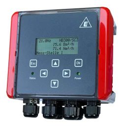
The CHP Efficiency Flow Computer GDR 1534 plays a central role in calculating the current gas volume. It is specifically designed to work with the Fluidistor gas flow meters GD 300 (Ex) and GD 500 (Ex). In addition, it can also process gas flow meters with a reed relay or open-collector output. This makes the GDR 1534 highly versatile and enables precise measurement of gas flow.
In addition to the gas flow rate, the methane content and the electrical power (via mA inputs) are also transmitted directly to the device. These measured values are crucial for determining the efficiency of the combined heat and power (CHP) plant, as they reflect the system’s energy yield and efficiency.
The GDR 1534 1-channel volume flow computer is used to precisely calculate the current gas volume based on readings from gas flow meters with differ- ent signal outputs. In addition, the device enables the determination of the efficiency of combined heat and power (CHP) plants.
Display and Counter
On an hourly or minutely basis, the current gas quan- tity can be displayed in cubic meters or liters. The total counter reading can be displayed in cubic meters or liters. The counter can have 9 digits up to 999 million cubic meters. The resolution is 0.1 liters.
Inputs: Gas flow meter
Inputs: Pressure and temperature
Pressure and temperature sensors can be connected via mA inputs. Alternatively, a Pt100 input is available for temperature measurement.
The integrated barometric sensor measures atmo- spheric pressure.
Calculation of the Standard Volume
Based on the operating volume determined by the connected gas flow meter and the measured values for pressure and temperature, the volume corrector calculates the standardized volume. The calculation of the standardization can be done according to the standards DIN 1343, DIN 6358, DIN ISO 2533 or DIN 102/ ISO 1-1975.
Inputs: Methane Content (CH4) and Electrical Output of the CHP Unit
To determine the efficiency, the relevant values for methane content and electrical output can each be transmitted to the device via an mA input.
Output and bus system
The 0(4) – 20 mA current output provides the current flow rate in the form of operating or standard cubic meters. Via 2 solid state relays, flow rates, device status, error messages or limit values can be transmit- ted to higher-level systems for further processing.
The Modbus RTU and Modbus TCP bus systems are available as an option for data transmission.


