Fluidistor – Gas Flowmeter – Overview

GD300-GD500

The Fluidistor gas flow meter GD 300 Ex / GD 500 Ex is used for gas volume measurements and for technical and medical gases.

The flow meters work on the principle of “fluidistor oscillator”. The measuring principle is dense independent and has no moving parts, thus there are no wearing parts in place and a recalibration is not necessary.

The Fluidistor gas flow meters are available from DN 15 – DN 400.

  • DN 15 – DN 25 (1/2″ – 1″) with an external pipe thread
  • DN 25 – DN 400 sandwich / Wafer
  • DN 40 – DN 400 with flange

Highlights

  • oscillating measuring principle suitable for almost all types of gas (including mixed gases), no moving components

  • measuring housing, orifice and measuring
    labyrinth made of stainless steel, also available as heavy duty construction

  • resistant to dirt, e.g. oil, rust, sulfur

  • excellent results measuring moist gases with condensate

  • mounting in falling direction into gas lines even for 100 % wet biogas due to integrated condensate drain

  • no influence on the measurement results with dirty, moist gases, e.g. sewage gas, biogas or contaminated industrial process gases

  • no influence on the measurement results for mixed gases with variable gas compositions
  • optional integrated ball valve (blocking valve) in the GD 300 for removal/installation of the platinum sensor without emptying the system

  • integrated calculator HB 300 in the measuring head with mA- (normalization optional) or pulse output

  • short response time T90 ≤ 50 ms
    with a flow velocity ≥ 0,25 m/s

  • high accuracy (±1,5 % of true value)

  • high reproducibility (0,1 % of true value)

  • low pressure loss

  • each flowmeter with calibration report

  • no recalibration required

  • ATEX certification: Ex II 1 / 2 G Ex ia / e mb IIC T4 Ga / Gb (certificate no. EX5 13 07 14689)

Application Areas

Sewage gas

Contamination and high water vapor saturation of the gas results with other measurement principles to erroneous measurements at the digester.

The Fluidistor is the functioning alternative!

Medical gases

Consumption measurement of oxygen, nitrous oxide, xenon, nitrogen, medical carbon dioxide and helium from total strand up to the healthcare beds or operating room with the Fluidistor

Hydrogen

Exact gas volume measurement of hydrogen

BIOGAS

Humidity and sulfur loads of several 100 ppm lead to measurement errors.

The Fluidistor is the functioning alternative!

Industrial gases

Quantity measurement of carbon dioxide (fermentation and cooling), argon (steel production), nitrogen, oxygen and natural gas (burner control, supply control of the boiler).

The Fluidistor also works with changing gas mixtures!

Compressed air controlling

Liter precise collection of consumption volume for billing purpose and identification of potential savings

Technical Data

GD 300 Ex Wafer - intermediate flange

GD300-WAVER

Nominal size:
DN 25 to DN 400

Process connection:
Wafer / sandwich / intermediate flange

Installation lenght: 65 mm

GD 300 Ex Flange

GD300-DN200

Nominal size: 
DN 40 to DN 400

Prozessanschluss:
flange acc. toEN-1092-1 or
DIN 2576, flange acc. to ASME B 16.5

Installation lenght:
depending on nominal size (300 – 500 mm)

GD 500 Ex external pipe thread

GD500

Nominal size: 
DN 15, DN 25

Process connection: 
external pipe thread
R 1/2”
G 1”

Installation lenght: 300 mm

With us you stay independent!

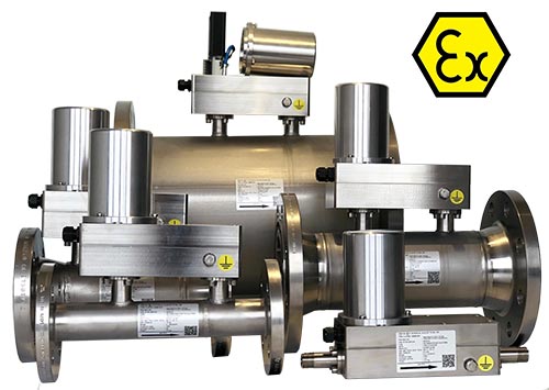
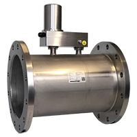
With the Fluidistor GD 300 Ex / GD 500 Ex you are completely independent concerning repair & maintenance.

The oscillating measuring method according to the Fluidistor principle requires no moving parts and no sensitive sensor materials, therefore an almost maintenance-free operation of the GD 300 Ex / GD 500 Ex is possible.

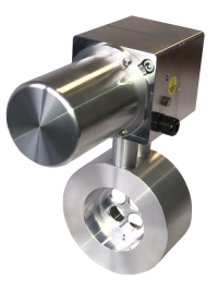
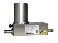
The integrated platinum wire sensor can be replaced without removing the gas flowmeter from the pipe system. A sensor change does not affect the calibration of the flow meter.

Recalibrations at regular intervals are not required and the cleaning of the flowmeter can be made directly on site. You can check the functionality of the sensors independently and gain independence from external resources.

You do not have to order  a service technician to come onsite or to remove the flow meter and send it in.

Project planning
Project planning GD 300/ GD 500
  • In the project planning, ensure that the pipe size is not increased by the gas meter in order to avoid false measurements.

  • The defined measurement ranges for individual nominal diameters must not be exceeded. A straight inlet zone of 10 x DN and an outlet zone of 5 x DN is required.

  • In the pipe network in front of the flowmeter, the gas velocity may not exceed supersonic speed.

  • Supercritical pressure drops and pulsating flows must be avoided.

  • When installing the GD 300/GD 500 under the ceiling, a distance of at least 25 cm from the lid to the ceiling must be complied, that the lid can be removed for connecting the sensor cable.

  • When installing the GD 300 Ex Wafer note that the lid is on the left-hand side, a minimum distance of 25 cm is required.
  • In case of falling below the Qmin (measuring range) display of measured values is not possible.

  •  The flowmeter GD 300 Ex / GD 500 Ex can be installed in a horizontal or vertical position. A condensate drain is integrated in the measuring head, which ensures the outflow of condensate of a 100% wet gas without sediments

  • The inclined measuring head ensures the outflow of condensate when installed in horizontal pipes.

The diagram applies to gases with a density of air at NTP (0°C and 1013 mbar). The decrease of pressure is always proportional to the gas density. If e.g. the operating pressure rises by 100% the pressure drop doubles.

Pressure loss

The diagram applies to gases with a density of air at NTP (0°C and 1013 mbar). The decrease of pressure is always proportional to the gas density. If e.g. the operating pressure rises by 100% the pressure drop doubles.

Pressure loss

Principle of Measurement

The flow meter GD 300 Ex / GD 500 Ex operates according to the principle of a „Fluidistor oscillator“. The gas passes the Fluidistor measuring head either directly or via an orifice in the main pipe.

The gas is discharged through the orifice into the Fluidistor measuring chamber. Directly behind the inlet there is a triangular damming body, which, due to the unstable middle position, forces the gas either to flow past on the right or left. At the level of the damming body in the right and left wall of the Fluidistor measuring chamber are two openings which are connected to each other by a channel. If the gas flows to the left from the damming body, a negative pressure is created on the left side wall or at the opening of the connecting channel.

This negative pressure is balanced through the right opening of the connecting channel. The pressure equalization of the negative pressure causes a change of flow direction from the left to the right side. The entire process is then repeated on the right side.

The period of time required for pressure equalization corresponds to a special amount of gas (litre/pulse), which has passed through the GD 300/GD 500. The frequency of the pressure equalization is proportional to the flow velocity.

The changing flow through the connecting channel is detected by a platinum wire (diameter 15 μ) in the connecting channel. A constant voltage is applied to the wire, which is permanently monitored. At the moment when the pressure equalization occurs in the connecting channel, the wire is not circulated around by gas for a short time and heats up due to the current flowing through the wire. This causes a temporary rise of the resistance in the platinum wire (like a Pt100 sensor) and the voltage drop (V=R*I) increases.

This increase in voltage is detected by the integrated calculator HB 300 Ex. Using the current output the measured value is directly transferred to a superior PLC system. Using the pulse output the signal is transferred to the external Flow Computer GDR 1501.

RELATED LINKS

Download

Translate »
WordPress Cookie Notice by Real Cookie Banner