- +49 6021-45 807-0
- 8:00 - 16:30 (CET)
- info@esters.de


Gas volume in cubic meters or liters with optional standardization for Fluidistor gas flow meter GD 300 (Ex) / GD 500 (Ex) and third-party gas flow meter with open collector, reed relay
4-line display with 20 characters per line
Multilingual menu (English, German, French, Spanish, Italian, Bulgarian, Polish, …)
Complete device configuration via keypad, no additional software required
Integrated WLAN hotspot with full device access via web browser
Optional LAN interface for integration into the plant network
Security code to protect configuration
Timestamped logging of important actions in the system logbook (device start, sensor failure, overrange, etc.)
UV-resistant polycarbonate housing material, protection class IP 65
Persistent counter readings for up to 5 years
Integrated real-time clock,
battery buffered for 5 years
Standardization according to DIN 1343, DIN 6358, DIN ISO 2533, DIN 102/ISO 1-1975
Freely scalable current output for output of actual flow rate
Adjustable pulse weighting
(0.1, 1 or 10 or 100 m³ per pulse)
Optional data transmission via Modbus RTU and Modbus TCP
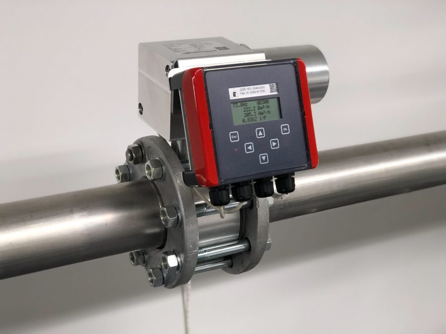
The 1-channel flow computer GDR 1530 G2 is used to calculate the current gas volume of the Fluidistor gas flow meter GD 300 (ex) / GD 500 (Ex) as well as gas flow meters with a reed relay or open collector output.
On an hourly or minutely basis, the current gas quantity can be displayed in cubic meters or liters. The total counter reading can be displayed in cubic meters or liters. The counter can have 9 digits up to 999 million cubic meters. The resolution is 0.1 liters.
Based on the operating volume determined by the connected gas flow meter and the measured values for pressure and temperature, the volume corrector calculates the standardized volume. The calculation of the standardization can be done according to the standards DIN 1343, DIN 6358, DIN 102/ ISO 1-1975.
Gas flow meter GD 300 (Ex)/ GD 500 (Ex):
Third-party products:
Inputs: Pressure and temperature
In addition to a pt100 input, the devices also have mA inputs for pressure and temperature sensors as well as an integrated barometric sensor for recording atmospheric pressure.
Output and bus system
The 0(4) – 20 mA current output provides the current flow rate in the form of operating or standard cubic meters. Via 2 solid state relays, flow rates, device status, error messages or limit values can be transmitted to higher-level systems for further processing.
The Modbus RTU and Modbus TCP bus systems are available as an option for data transmission.
All parameter settings/configurations can be carried out using the keys and the display or with a web browser via the integrated WLAN hotspot.